Front Panel Description
The device's front panel is shown in the following figure and described in the subsequent table.
Front Panel
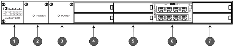
The previous figure provides only an example of the Mediant 2600 hardware configuration; module slot locations and type of modules (e.g., Media Processing Module) depend on the ordered hardware configuration.
Front-Panel Description
|
Item # |
Component Description |
||||||
|---|---|---|---|---|---|---|---|
|
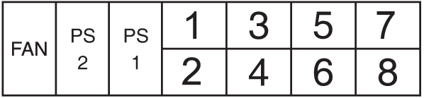
1 |
Fan Tray module with a schematic displayed on its front panel showing the chassis' slot numbers. For more information on this module, see Fan Tray Module. The following figure shows the location of the Fan Tray module, Power Supply modules, and chassis slot numbers:
|
||||||
|
2 |
Power Supply module No. 2. For more information, see Power Supply Modules. |
||||||
|
3 |
Power Supply module No. 1. For more information, see Power Supply Modules. |
||||||
|
4 |
Slots 1-2, shown covered with blank AMC modules for unused AMC slots. These slots house the optional, Media Processing Module (MPM). Note: The MPM is a customer-ordered item. |
||||||
|
5 |
Slots 3-4, covered with blank AMC modules for unused AMC slots. Note:
|
||||||
|
6 |
Slot 5-6 with E-SBC CPU AMC module (hereafter referred to as E-SBC), providing CPU, serial interface, and Ethernet interface functionalities. For more information, see E-SBC Module. Note: If you purchased this device in an initial release, the E-SBC module may be occupied in Slots 3-4 (instead of Slots 5-6). |
||||||
|
7 |
Slots 7-8, covered with blank covers for unused AMC slots. Note: These slots are currently reserved for future use. |